概述
本篇是“练习项目”系列的第三篇,主要介绍一下利用表面凹凸技术提升物体的表面细节。为了提升模型表面的细节,一个可以想到的方式是制作更加复杂的网格,但这是不可取的。一方面会增加美术人员的工作量;另一方面,也会对机器的性能造成很大的消耗。本篇文章,将介绍一些表面凹凸的技术,来达到提高表面细节的目的。
一、凹凸贴图(Bump Mapping)
这种技术,使用高度图来计算法线。给定一张高度图,通过计算相邻像素的高度差值来改变表面法向量。
为了计算(u,v)处的法向量,要经过以下几步。
第一步,在(u-1,v)和(u+1,v)处采样高度图,得到高度值u1、u2。由此,可以得到二者之间的差值du。进而,可以得到x方向的切向量:\(tu = (1,0,du)\)。
第二步,在(u,v-1)和(u,v+1)处采样高度图,得到高度值v1、v2。由此,可以得到二者之间的差值dv。进而,可以得到y方向的切向量:\(tv = (0,1,dv)\)。
第三步,tu和tv进行叉乘,从而得到法向量。
主要的代码如下:
1
2
3
4
5
6
7
8
9
10
11
12
13
14
| float3 CalculateNormal(float2 uv)
{
float2 du = float2(_DepthMap_TexelSize.x * 0.5,0);
float u1 = SAMPLE_TEXTURE2D(_DepthMap,sampler_DepthMap,uv - du).r;
float u2 = SAMPLE_TEXTURE2D(_DepthMap,sampler_DepthMap,uv + du).r;
float3 tu = float3(1,0,(u2 - u1)*_Scale);
float2 dv = float2(0,_DepthMap_TexelSize.y * 0.5);
float v1 = SAMPLE_TEXTURE2D(_DepthMap,sampler_DepthMap,uv - dv).r;
float v2 = SAMPLE_TEXTURE2D(_DepthMap,sampler_DepthMap,uv + dv).r;
float3 tv = float3(0,1,(v2 - v1)*_Scale);
return normalize(-cross(tu,tv));
}
|

代码
二、法线贴图(Normal Mapping)
法线贴图,在实际的生产过程中,应该是使用频率比较高的表面凹凸技术。恰好之前写了一篇关于法线贴图的文章,这里就不再赘述,有兴趣的可以去看一下。法线贴图那些事儿。

代码
三、视差贴图(Parallax
Mapping)
根据视线方向与高度图(深度图)的交点,找到新的UV。
示意图如下:

实际使用的时候,要准确求得交点,计算量很大,因此会选择使用一些近似的方案。
1、视差贴图简单版
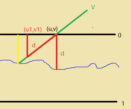
直接根据当前UV采样的高度值,然后将该高度值乘以视线方向(单位向量),进而得到新的UV值。
如下图所示,我们根据当前的(u,v)得到深度值为d,然后将深度值乘以视线方向,能得到新的(u1,v1),可以看见该结果还是离准确的结果(黄色)比较近的。

计算新的UV的主要代码如下:
1
2
3
4
5
6
7
8
| float2 ParallaxMapping(float2 uv, float3 viewDir_tangent)
{
float3 viewDir = normalize(viewDir_tangent);
float height = SAMPLE_TEXTURE2D(_DepthMap, sampler_DepthMap, uv).r;
float2 p = viewDir.xy / viewDir.z * (height * _HeightScale);
return uv - p;
}
|

在视差贴图的那个平面里你仍然能看到在边上有古怪的失真。原因是在平面的边缘上,纹理坐标超出了0到1的范围进行采样,根据纹理的环绕方式导致了不真实的结果。解决的方法是当它超出默认纹理坐标范围进行采样的时候就丢弃这个片元:
1
2
| if (uv.x > 1.0 || uv.y > 1.0 || uv.x < 0.0 || uv.y < 0.0) //去掉边上的一些古怪的失真,在平面上工作得挺好的
discard;
|
可以看见该简单版的实现很简单,但是效果并不十分好,只能用在平缓的凹凸面上,但表面凹凸很明显时,会有明显的失真。通过分析下面这张图就能知道为什么凹凸明显时会失真:

代码
2、带偏移量限制的视差贴图
(Parallax Mapping with offset limiting)
为了减轻视线与平面十分持平时(V.z很小导致偏移量过大)产生的怪异效果,可以去掉除以V.z这一步。
1
2
3
4
5
6
7
8
| float2 ParallaxMapping(float2 uv, float3 viewDir_tangent)
{
float3 viewDir = normalize(viewDir_tangent);
float height = SAMPLE_TEXTURE2D(_DepthMap, sampler_DepthMap, uv).r;
float2 p = viewDir.xy * (height * _HeightScale);
return uv - p;
}
|

代码
3、陡峭视差贴图 (Steep
Parallax Mapping)
陡峭视差贴图(Steep Parallax
Mapping)是视差贴图的扩展,原则是一样的,但不是使用一个样本而是多个样本来计算新的UV。即使在陡峭的高度变化的情况下,它也能得到更好的结果,原因在于该技术通过增加采样的数量提高了精确性。
陡峭视差贴图的基本思想是将总深度范围划分为同一个深度/高度的多个层。从每个层中我们沿着视线方向移动采样纹理坐标,直到我们找到一个采样低于当前层的深度值。

步骤如下:
找到视线方向与第0层的交点\(T_0\),层深度是0.0,对应深度值为0.75,因为该点在深度图之上,所以找下一个点。
找到视线方向与第1层的交点\(T_1\),层深度是0.125,对应深度值为0.625,因为该点在深度图之上,所以找下一个点。
找到视线方向与第2层的交点\(T_2\),层深度是0.25,对应深度值为0.4,因为该点在深度图之上,所以找下一个点。
找到视线方向与第3层的交点\(T_3\),层深度是0.375,对应深度值为0.2,因为该点在深度图之下,所以这就是我们要找的点。
主要的代码如下:
1
2
3
4
5
6
7
8
9
10
11
12
13
14
15
16
17
18
19
20
21
22
23
24
25
| float2 ParallaxMapping(float2 uv, float3 viewDir_tangent)
{
float3 viewDir = normalize(viewDir_tangent);
float layerNum = lerp(_MaxLayerNum, _MinLayerNum, abs(dot(float3(0, 0, 1), viewDir)));
float layerDepth = 1.0 / layerNum;
float currentLayerDepth = 0.0;
float2 deltaTexCoords = viewDir.xy / viewDir.z / layerNum * _HeightScale;
float2 currentTexCoords = uv;
float currentDepthMapValue = SAMPLE_TEXTURE2D(_DepthMap, sampler_DepthMap, currentTexCoords).r;
while(currentLayerDepth < currentDepthMapValue)
{
currentTexCoords -= deltaTexCoords;
currentDepthMapValue = SAMPLE_TEXTURE2D_LOD(_DepthMap, sampler_DepthMap, currentTexCoords, 0).r;
currentLayerDepth += layerDepth;
}
return currentTexCoords;
}
|

代码
4、浮雕视差贴图 (Relief
Parallax Mapping)
该方法是对陡峭视差贴图的进一步优化。在陡峭视差贴图的基础上,利用二分查找来细化结果。
如下图,假设我们利用陡峭视差贴图找到了T3,而T是准确的交点,二分查找的次数为3。

步骤:
取\(T_2\)和\(T_3\)的中点\(P_1\),因为\(P_1\)在下面,因此用\(P_1\)取代\(T_3\)
取\(T_2\)和\(P_1\)的中点\(P_2\),因为\(P_2\)在上面,因此用\(P_2\)取代\(T_2\)
取\(P_2\)和\(P_1\)的中点\(P_3\),因为\(P_3\)在下面,因此用\(P_3\)取代\(P_1\)
到达二分查找次数上限,结果为\(P_3\)。
主要代码如下:
1
2
3
4
5
6
7
8
9
10
11
12
13
14
15
16
17
18
19
20
21
22
23
24
25
26
27
28
29
30
31
32
33
34
35
36
37
38
39
40
41
42
43
44
45
46
47
48
49
50
| float2 ParallaxMapping(float2 uv, float3 viewDir_tangent)
{
float layerNum = lerp(_MinLayerNum, _MaxLayerNum, abs(dot(float3(0, 0, 1), viewDir_tangent)));
float layerDepth = 1.0 / layerNum;
float currentLayerDepth = 0.0;
float2 deltaUV = viewDir_tangent.xy / viewDir_tangent.z * _HeightScale / layerNum;
float2 currentTexCoords = uv;
float currentDepthMapValue = SAMPLE_TEXTURE2D(_DepthMap, sampler_DepthMap, currentTexCoords).r;
while(currentLayerDepth < currentDepthMapValue)
{
currentTexCoords -= deltaUV;
currentDepthMapValue = SAMPLE_TEXTURE2D_LOD(_DepthMap, sampler_DepthMap, currentTexCoords, 0).r;
currentLayerDepth += layerDepth;
}
float2 halfDeltaUV = deltaUV / 2;
float halfLayerDepth = layerDepth / 2;
currentTexCoords += halfDeltaUV;
currentLayerDepth -= halfLayerDepth;
int numSearches = 5;
for (int i = 0; i < numSearches; i ++)
{
halfDeltaUV = halfDeltaUV / 2;
halfLayerDepth = halfLayerDepth / 2;
currentDepthMapValue = SAMPLE_TEXTURE2D_LOD(_DepthMap, sampler_DepthMap, currentTexCoords, 0).r;
if (currentDepthMapValue > currentLayerDepth)
{
currentTexCoords -= halfDeltaUV;
currentLayerDepth += halfLayerDepth;
}
else
{
currentTexCoords += halfDeltaUV;
currentLayerDepth -= halfLayerDepth;
}
}
return currentTexCoords;
}
|

代码
5、视差遮蔽贴图
(Parallax Occlusion Mapping, POM)
视差遮蔽贴图(Parallax Occlusion
Mapping)和陡峭视差贴图的原则相同,但不是用触碰的第一个深度层的纹理坐标,而是在触碰之前和之后,在深度层之间进行线性插值。我们根据表面的高度距离啷个深度层的深度层值的距离来确定线性插值的大小。
利用陡峭视差贴图得到最靠近交点的\(T_2\)和\(T_3\)后,根据这两者的深度与对应层深度的差值作为比例进行插值。
看看下面的图片就能了解它是如何工作的:

主要代码如下:
1
2
3
4
5
6
7
8
9
10
| float2 prevTexCoords = currentTexCoords + deltaTexCoords;
float prevLayerDepth = currentLayerDepth - layerDepth;
float afterDepth = currentDepthMapValue - currentLayerDepth;
float beforeDepth = SAMPLE_TEXTURE2D(_DepthMap, sampler_DepthMap, prevTexCoords).r - prevLayerDepth;
float weight = afterDepth / (afterDepth - beforeDepth);
float2 finalTexCoords = prevTexCoords * weight + currentTexCoords * (1.0 - weight);
return finalTexCoords;
|

代码
6、带自阴影的视差贴图
上面的几种视差贴图都没有考虑自阴影(即凸起部分能向其他部分投射阴影)。要实现自阴影也不难,和制作深度图一样,此时沿着光线方向指向我们利用视差贴图找到的交点,然后判断该交点是否被其他部分遮蔽了。
实际上大部分操作和视差贴图类似,只是把操作的向量从视线向量改为光线向量而已。

主要的代码如下:
1
2
3
4
5
6
7
8
9
10
11
12
13
14
15
16
17
18
19
20
21
22
23
24
25
26
27
28
29
30
31
32
33
34
35
36
| float ParallaxShadow(float3 lightDir_tangent, float2 initialUV, float initialHeight)
{
float3 lightDir = normalize(lightDir_tangent);
float shadowMultiplier = 1;
const float minLayers = 15;
const float maxLayers = 30;
if (dot(float3(0, 0, 1), lightDir) > 0)
{
float numSamplesUnderSurface = 0;
float numLayers = lerp(maxLayers, minLayers, abs(dot(float3(0, 0, 1), lightDir)));
float layerHeight = 1 / numLayers;
float2 texStep = _HeightScale * lightDir.xy / lightDir.z / numLayers;
float currentLayerHeight = initialHeight - layerHeight;
float2 currentTexCoords = initialUV + texStep;
float heightFromTexture = SAMPLE_TEXTURE2D(_DepthMap, sampler_DepthMap, currentTexCoords).r;
while(currentLayerHeight > 0)
{
if (heightFromTexture <= currentLayerHeight)
numSamplesUnderSurface += 1;
currentLayerHeight -= layerHeight;
currentTexCoords += texStep;
heightFromTexture = SAMPLE_TEXTURE2D_LOD(_DepthMap, sampler_DepthMap, currentTexCoords, 0).r;
}
shadowMultiplier = 1 - numSamplesUnderSurface / numLayers;
}
return shadowMultiplier;
}
|

代码
7、带软自阴影的视差贴图
为了美化上面的自阴影效果,这里使用软阴影。
主要的代码如下:
1
2
3
4
5
6
7
8
9
10
11
12
13
14
15
16
17
18
19
20
21
22
23
| while(currentLayerHeight > 0)
{
if (heightFromTexture < currentLayerHeight)
{
numSamplesUnderSurface += 1;
float newShadowMultiplier = (currentLayerHeight - heightFromTexture) * (1.0 - stepIndex / numLayers);
shadowMultiplier = max(shadowMultiplier, newShadowMultiplier);
}
stepIndex += 1;
currentLayerHeight -= layerHeight;
currentTexCoords += texStep;
heightFromTexture = SAMPLE_TEXTURE2D_LOD(_DepthMap, sampler_DepthMap, currentTexCoords, 0).r;
}
if(numSamplesUnderSurface < 1)
{
shadowMultiplier = 1;
}
else
{
shadowMultiplier = 1.0 - shadowMultiplier;
}
|

代码
参考


